
A Layer 2 switch forwards Ethernet frames using MAC addresses within a single broadcast domain; a Layer 3 switch adds IP-based routing so traffic can move between subnets and VLANs without leaving the switch. For a simple flat network or a pure access layer, Layer 2 is cheaper, faster to deploy, and easier to manage. Once you have multiple VLANs that need to talk to each other, or you want routing policy close to the edge, Layer 3 belongs at the distribution or core tier. The cost and configuration complexity jump noticeably, so the decision should always be driven by architecture, not by the assumption that more layers means better.
Table of Contents
- How do Layer 2 and Layer 3 switches compare?
- What does "layer" actually mean here?
- How Layer 2 switching actually works
- How Layer 3 switching and routing work
- Feature-by-feature trade-offs worth knowing
- When should you choose a Layer 2 vs Layer 3 switch?
- How can you tell if a switch is Layer 2, Layer 2+, or Layer 3?
- What neither switch type replaces, and pitfalls to avoid
- Key Takeaways
- The architecture choice nobody talks about honestly
- Useful sources for further reading
How do Layer 2 and Layer 3 switches compare?
| Dimension | Layer 2 Switch | Layer 3 Switch |
|---|---|---|
| Forwarding basis | MAC address table | IP routing table + MAC table |
| Inter-VLAN routing | Requires an external router | Native, via Switch Virtual Interfaces (SVIs) |
| Broadcast domain handling | Single broadcast domain per switch (VLANs segment logically) | Multiple broadcast domains; routing boundaries contain broadcasts |
| Supported protocols | Ethernet, ARP, STP, VLAN tagging (802.1Q) | All L2 protocols + IP, ICMP, static routes, OSPF, RIP, EIGRP (tier-dependent) |
| ACLs and security | Limited; no IP-level filtering | IP-based ACLs; stateless on most platforms |
| Throughput and latency | Wire-speed ASIC switching; very low latency | ASIC-based routing also near wire-speed for LAN traffic |
| Management features | VLAN assignment, STP, port security | All L2 features + routing protocols, routing policy, QoS per subnet |
| Typical deployment layer | Access layer, small/flat networks | Distribution layer, core, multi-VLAN campus networks |
| Cost and complexity | Lower cost; minimal configuration | Higher cost; requires routing design and SVI configuration |
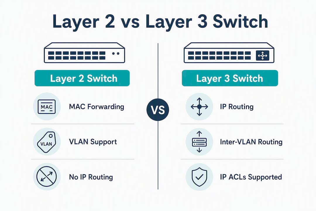
What does "layer" actually mean here?
The OSI model defines seven layers of network communication. Two of them matter for this comparison.
Layer 2 (Data Link) handles communication between devices on the same physical or logical network segment. It uses MAC addresses, which are hardware identifiers burned into every network interface at the factory. Layer 2 is where Ethernet frames live.
Layer 3 (Network) handles communication between different networks or subnets. It uses IP addresses, which are logical and assignable. Layer 3 is where packets get routed toward a destination that may be on a completely different segment.
Key protocols at each layer:
- Layer 2: Ethernet, ARP (Address Resolution Protocol), STP (Spanning Tree Protocol), 802.1Q VLAN tagging
- Layer 3: IP, ICMP, static routes, OSPF, RIP, EIGRP, BGP (protocol availability varies by hardware tier)
VLANs sit at Layer 2 by definition. They segment a physical switch into multiple logical broadcast domains. But traffic between two VLANs must cross a Layer 3 boundary, which is exactly why inter-VLAN routing requires either an external router or a Layer 3 switch.
How Layer 2 switching actually works
A Layer 2 switch builds its MAC address table by watching incoming frames. When a frame arrives on a port, the switch records the source MAC address and the port it came in on. The next time a frame arrives destined for that MAC, the switch sends it directly to the right port instead of guessing.
What happens when the destination MAC is unknown? The switch floods the frame out every port except the one it arrived on. The same flooding behavior applies to broadcast traffic, such as ARP requests. Every device in the broadcast domain receives that frame, which is fine on a small network and a real problem on a large one.
On large Layer 2 networks, broadcast storms are a genuine operational risk. A single misconfigured NIC or a network loop can generate enough broadcast traffic to saturate links and bring down connectivity for every device in the domain. VLANs reduce the blast radius, but they do not eliminate the underlying vulnerability.
VLANs on a Layer 2 switch work by assigning ports to specific VLAN IDs. Frames tagged with 802.1Q headers carry their VLAN membership across trunk links. What a Layer 2 switch cannot do is route traffic from VLAN 10 to VLAN 20. That packet has to leave the switch, hit a router (or an L3 switch), and come back. In high-traffic environments, that round-trip adds latency and creates a bottleneck at the router.
Spanning Tree Protocol (STP) exists to prevent loops in Layer 2 networks. When you connect switches together for redundancy, you create the possibility of a frame circling forever. STP detects those loops and blocks redundant paths, keeping exactly one active path between any two points. Without it, a broadcast storm would take down the network almost instantly.
Pro Tip: When deploying VoIP on a Layer 2 access switch, always put voice traffic on a dedicated VLAN and configure QoS markings at the port level. Without a separate voice VLAN, voice frames compete with data frames in the same broadcast domain, and jitter becomes unpredictable under load. This applies whether you have one switch or twenty.
| Layer 2 behavior | What triggers it |
|---|---|
| Unicast forwarding | Destination MAC is in the table |
| Flooding | Destination MAC is unknown |
| Broadcast forwarding | Destination is FF:FF:FF:FF:FF:FF |
| VLAN filtering | Port VLAN membership and 802.1Q tags |
| STP port blocking | Loop detected in topology |
How Layer 3 switching and routing work
A Layer 3 switch does everything a Layer 2 switch does, then adds a routing engine on top. The routing engine uses IP addresses and a routing table to make forwarding decisions when traffic needs to cross a subnet boundary.

The mechanism that makes inter-VLAN routing possible on an L3 switch is the Switch Virtual Interface (SVI). An SVI is a logical Layer 3 interface assigned to a VLAN. You create an SVI for each VLAN, assign it an IP address in that VLAN's subnet, and configure hosts to use that IP as their default gateway. Traffic from VLAN 10 destined for VLAN 20 hits the SVI for VLAN 10, gets routed to the SVI for VLAN 20, and arrives at the destination without ever touching an external router.
The routing lookup itself works differently from a MAC lookup. The switch checks the destination IP against its routing table, finds the longest matching prefix, identifies the next-hop IP, resolves that to a MAC address via ARP, and then forwards the frame. On a hardware-based L3 switch, all of this happens in an ASIC at near wire-speed, which is why hardware-based inter-VLAN routing can outperform a software router handling the same traffic.
Routing protocol support varies significantly by hardware tier:
- Static routing only — common on entry-level L3 switches; you manually define every route.
- RIP — distance-vector protocol; supported on many mid-tier switches but rarely used in new designs.
- OSPF — link-state protocol; available on mid- and high-tier switches; the standard for enterprise campus routing.
- EIGRP — Cisco-proprietary; available on Cisco hardware at mid/high tiers.
- BGP — typically reserved for high-end switches or dedicated routers; rarely needed inside a campus LAN.
Entry-level L3 switches often support only static routing. Before you design a network around OSPF or EIGRP on a distribution switch, check the datasheet for the specific routing protocols supported and the size of the L3 forwarding table. A switch that advertises "Layer 3 capable" may mean nothing more than static routes.
To confirm routing is enabled on a switch you are evaluating, look for these generic CLI indicators:
show ip routereturns a populated routing table (not just a default gateway entry)show ip interface briefshows SVIs with IP addresses assigned and status "up/up"show running-configcontainsinterface vlan [ID]entries withip addressstatementsip routingappears in the global configuration
Pro Tip: Before committing to an L3 switch for a distribution role, pull the datasheet and look for two numbers: the L3 forwarding table (FIB) size and the number of supported LPM (Longest Prefix Match) entries. A switch with a small FIB will handle a campus LAN fine today but may struggle if you add subnets or routing peers later.
Feature-by-feature trade-offs worth knowing
Protocol depth and hardware tiers
Both switch types support Ethernet and VLANs. The gap opens at Layer 3. An L3 switch at the low end may handle only static routes, while a mid-tier device adds OSPF. Full BGP support is rare outside high-end platforms. This matters because a network designed around dynamic routing needs hardware that actually supports it. Buying a switch labeled "L3" and discovering it only does static routes mid-project is a common and avoidable mistake.
ACLs: useful but not a firewall
Layer 3 switches support IP-based ACLs, which let you permit or deny traffic between subnets. The catch is that ACLs on most L3 switches are stateless. A stateless ACL does not track connection state. If you permit TCP traffic from VLAN 10 to VLAN 20, you also need an explicit rule permitting the return traffic from VLAN 20 back to VLAN 10. A dedicated firewall handles this automatically through stateful inspection. An L3 switch does not. Engineers who treat an L3 switch's ACL as a firewall equivalent end up with either broken connectivity or unintended open paths.
Layer 2 switches have no IP-level filtering at all. They can enforce port security based on MAC addresses, but they cannot block traffic between IP addresses on the same VLAN.
Performance: where the difference is smaller than you think
Modern Layer 2 switches forward frames at line rate using ASICs. Layer 3 switches do the same for routed traffic, as long as the routing table fits in hardware. The performance difference between L2 switching and L3 routing on a quality switch is minimal for LAN traffic. Where L3 switches fall behind dedicated routers is on WAN-facing features: NAT, VPN termination, stateful deep packet inspection. Those tasks are typically handled in software or specialized hardware that most L3 switches do not carry.
Scale limits and FIB overflow
When an L3 switch's forwarding table fills up, some platforms fall back to CPU-based forwarding for overflow routes. That fallback causes a measurable drop in throughput and a spike in latency. For a campus network with a few dozen subnets, this is rarely a concern. For a large enterprise or a network that peers with external routing domains, it is worth checking the FIB capacity before deployment.
Pro Tip: If you are deploying an L3 switch at distribution and plan to redistribute routes from multiple VLANs plus a WAN link, add up your expected route count before you buy. A switch with a 1,000-entry FIB sounds generous until you account for host routes, summary routes, and any future growth.
When should you choose a Layer 2 vs Layer 3 switch?
The right answer starts with a few direct questions about your network.
- How many VLANs do you have, and do they need to communicate with each other?
- How much traffic crosses VLAN boundaries on a typical day?
- Do you need IP-level ACLs or QoS policies between subnets?
- Is there already a router or firewall handling inter-VLAN routing at the edge?
- What is your budget and your team's comfort level with routing configuration?
If your answers point to a single VLAN, minimal inter-subnet traffic, and an existing router handling everything else, Layer 2 is the right tool. It is cheaper, simpler, and there is no routing configuration to get wrong.
Use Layer 2 when:
- The network is flat or has one or two VLANs
- An external router or firewall already handles all routing
- Budget is constrained and routing features are not needed
- The deployment is an access layer feeding into a distribution switch
Use Layer 3 when:
- Multiple VLANs need to exchange traffic frequently
- You want to eliminate the external router hop for LAN-to-LAN traffic
- You need IP-based ACLs or per-subnet QoS at the distribution layer
- The network is a campus or multi-department environment
Real-world deployment scenarios
Small office (10–30 users, one VLAN): A Layer 2 access switch connected to a firewall/router at the edge covers everything. Adding an L3 switch here is over-engineering. For VoIP deployments in this environment, a voice VLAN on the L2 switch with QoS markings is sufficient.

Multi-department office (50–200 users, 4–8 VLANs): This is where L3 at distribution pays off. Each department gets its own VLAN, the L3 switch routes between them at wire speed, and the firewall at the edge handles only WAN-bound traffic. Multi-site operations with voice across locations benefit from this design because inter-VLAN voice traffic stays local and low-latency.
Multi-tenant building or campus: L3 switches at the distribution/core layer with L2 switches at each floor or tenant access point. This hierarchical design balances port density, cost, and routing performance. Tenants get isolated VLANs; the L3 core handles routing between shared services.
Pro Tip: The hybrid model, L2 at access and L3 at distribution/core, is the right architecture for most enterprise networks. It keeps access switches cheap and simple while centralizing routing policy where it is easier to manage and audit.
How can you tell if a switch is Layer 2, Layer 2+, or Layer 3?
Not every switch that ships with "L3" in the marketing copy supports the same feature set. Here is how to verify before you commit.
Datasheet checklist
- Look for SVI support — the datasheet should explicitly mention Switch Virtual Interfaces or "inter-VLAN routing."
- Check routing protocols listed — static only, or does it include OSPF, RIP, EIGRP?
- Find the L3 forwarding table size (FIB entries or LPM entries) — a number in the hundreds may be limiting.
- Check for WAN interfaces — their absence confirms this is a LAN-only device.
- Look for ACL support — note whether it is L2 MAC-based or L3 IP-based.
CLI verification on a live device
| Command | What to look for |
|---|---|
show ip route | Populated routing table with subnet entries |
show ip interface brief | SVIs listed with IP addresses and "up/up" status |
show running-config | interface vlan X blocks with ip address lines |
show version or show platform | Feature set or license tier that enables routing |
Understanding "Layer 2+"
Some switches are marketed as Layer 2+ or "basic L3." This usually means they support static routing and possibly RIP, but not OSPF or EIGRP. They can route between a small number of directly connected subnets but are not suited for dynamic routing environments. If a vendor uses "L2+" without specifying which protocols are supported, treat it as static-routing-only until the datasheet confirms otherwise.
Pro Tip: On a live network, the fastest indicator that a switch is doing L3 routing is the presence of multiple interface vlan entries in the running config, each with a unique IP address. If you only see one, the switch is likely acting as a pure L2 device with a management IP.
What neither switch type replaces, and pitfalls to avoid
WAN and edge limitations
Layer 3 switches are built for LAN routing. Most lack the WAN interfaces, NAT capability, VPN termination, and stateful deep packet inspection that edge routers and firewalls provide. Connecting an L3 switch directly to an ISP handoff and expecting it to handle NAT and VPN is a design error that shows up in production at the worst possible time. Keep a dedicated router or firewall at the perimeter.
Common misconfigurations
- Overloading an access switch with routing tasks. An access switch handling inter-VLAN routing for hundreds of hosts adds CPU overhead and creates a single point of failure for routing. Push routing up to the distribution layer.
- Wrong SVI configuration. An SVI that is administratively down, or assigned to the wrong subnet, silently breaks inter-VLAN connectivity. Hosts see the gateway as unreachable even though the switch is physically fine.
- Undersized FIB. Adding routes beyond the hardware table limit triggers CPU-based forwarding fallback, which degrades performance without any obvious error message.
- Treating L3 ACLs as a firewall. Stateless ACL rules require bidirectional entries. Missing the return-traffic rule blocks legitimate sessions and generates confusing troubleshooting tickets.
ACLs on most Layer 3 switches are stateless filters, not stateful firewalls. An ACL that permits traffic from subnet A to subnet B does not automatically permit the return traffic. You must write both directions explicitly, or use a dedicated firewall for stateful inspection.
Security implications specific to each layer
Layer 2 networks are vulnerable to ARP spoofing, MAC flooding, and VLAN hopping if trunk ports are misconfigured. None of these attacks require IP-level access. Layer 3 adds IP-level segmentation and ACL enforcement, which raises the bar, but the stateless nature of switch ACLs means the attack surface is not as contained as it would be behind a firewall. For environments with compliance requirements, financial data, or sensitive voice traffic, a dedicated firewall at the perimeter remains non-optional regardless of whether you use L2 or L3 switching internally.
Key Takeaways
Layer 2 switches belong at the access layer for simple, flat networks; Layer 3 switches belong at distribution or core wherever VLANs need to route traffic between each other.
| Point | Details |
|---|---|
| Core forwarding difference | Layer 2 uses MAC addresses; Layer 3 adds IP routing between subnets and VLANs. |
| Access vs distribution rule | Deploy L2 at the access layer and L3 at distribution or core for most enterprise designs. |
| VLAN count drives the decision | If multiple VLANs need to communicate frequently, L3 inter-VLAN routing eliminates the external router hop. |
| ACLs are not firewalls | L3 switch ACLs are stateless; always pair with a dedicated edge firewall for stateful security. |
| Verify before you buy | Check the datasheet for SVI support, routing protocols, and FIB size before committing to an L3 switch. |
The architecture choice nobody talks about honestly
The framing of "L2 vs L3" often misleads people into thinking one is simply better than the other. It is not a quality ranking. It is a placement decision.
The networks that get into trouble are the ones where someone bought an L3 switch because it sounded more capable, then configured it as a pure L2 device because nobody on the team had time to set up SVIs properly. Now you have a more expensive switch doing less than a cheaper one would have, with routing features sitting idle and adding complexity to firmware upgrades and audits.
The opposite mistake is just as common: a growing office with six VLANs and a single L2 access switch routing everything through a firewall that was never sized for that traffic. Voice calls drop. File transfers slow down. The firewall CPU spikes at 9 AM every day. The fix is a $400 L3 distribution switch, but nobody bought one because "we already have a switch."
The practical rule is straightforward. If you have one or two VLANs and a router at the edge, stay with L2 at the access layer. The moment inter-VLAN traffic becomes a bottleneck, or you need per-subnet QoS for voice, move routing to an L3 switch at distribution. That is the architecture Businessvoip's team applies when designing on-site VoIP networks: voice on its own VLAN, data on another, L3 routing at the distribution tier so voice traffic never has to fight for bandwidth at the firewall. For multi-site deployments, the same logic extends across locations, with each site's access layer staying simple and the routing intelligence sitting where it can be managed centrally.
If you are designing a network for a VoIP deployment and want the switching layer built right from the start, Businessvoip's on-site installation team handles the full design, cabling, and configuration so the network is ready before the phones arrive.
Useful sources for further reading
The following sources informed this article and are worth bookmarking for deeper reference:
- Domotz: Layer 2 vs Layer 3 Switch Guide — Practical overview of forwarding differences, VLAN behavior, and when each switch type fits. Good starting point for network designers.
- Cisco Meraki Documentation: Comparing L3 and L2 Switches — Authoritative reference for SVI configuration, hierarchical design, and broadcast domain behavior. Use this for configuration guidance.
- RAD: Layer 2 vs Layer 3 Switching Explained — Clear explanation of hardware-based routing performance and LAN-to-LAN throughput advantages of L3 switches.
- Come-Star: Layer 2 vs Layer 3 Switch — Covers ACL statelessness and security implications; useful for engineers evaluating switch-based access control.
- ServerFault: Layer 2 vs Layer 3 Switches — Practitioner discussion on routing protocol support tiers and datasheet verification; good for real-world sanity checks.
- GeeksforGeeks: Difference Between Layer 2 and Layer 3 Switches — Concise reference table and protocol-level breakdown; useful for students building foundational knowledge.
- CompTIA: Understanding Layers 2 and 3 of the OSI Model — Authoritative OSI model explanation from a certification body; use for grounding any Layer 2/3 discussion in the OSI framework.
- Allied Telesis: What Does Layer 2 and Layer 3 Networking Mean? — Hardware vendor perspective on MAC vs IP addressing and how switches use both layers together.
- ITU Online: Understanding the Differences Between Layer 2 and Layer 3 Switches — Training-focused breakdown with forwarding comparison tables; good supplementary reading for networking students.
- ManageEngine OpUtils: Layer 2 vs Layer 3 Switches — Covers scalability, QoS, and security feature comparisons in a structured format; useful for procurement decision-making.